Application Of Servomechanism As A Closed Loop Feedback
ABSTRACT
Servomechanism refers to a device or combination of devices that automatically controls a mechanism or a source of power or energy. Servomechanisms automatically compare the controlled output of a mechanism to the controlling input. The difference between the settings or positions of the output and the input is called the error signal, which regulates the output to a desired value. Servomechanisms may be mechanical, electrical, hydraulic, or optical. The process of sending the error signal back for comparison with the input is called feedback, and the whole process of the input, output, error signal, and feedback is called a closed loop. The closed-loop system, also known as a servomechanism, has some means of incorporating mechanical feedback from the output to the input. A sensor at the output end generates a signal that is sent back to the input to regulate the machine behavior. The term servomechanism correctly applies only to systems where feedback or error-correction signals help control mechanical position or other parameters. For example, an automotive power window control is not a servomechanism; because there is no automatic feedback which controls position the operator does this by observation. By contrast the car’s cruise control uses closed loop feedback, which classifies it as a servomechanism.
Servos can be used to generate linear or circular motion depending on their type. The makeup of a typical servo includes a DC motor, a gear train, a potentiometer, an integrated circuit (IC) and an output shaft. The desired servo position is input and comes in as a coded signal to the IC. The IC directs the motor to go, driving the motor’s energy through gears that set the speed and desired direction of movement until the signal from the potentiometer provides feedback that the desired position is reached and the IC stops the motor.

The potentiometer makes controlled motion possible by relaying the current position while allowing for correction from outside forces acting on control surfaces: once the surface is moved, the potentiometer provides the signal of position and the IC signals the necessary motor movement until the correct position is regained.
A combination of servos and multi-geared electric motors can be organized together to perform more complex tasks in various types of systems including robots, vehicles, manufacturing and wireless sensor and actuator network.
CHAPTER ONE
- INTRODUCTION
1.1 BACKGROUND OF THE STUDY
A servomechanism system is a closed-loop control system used to determine the position, velocity, and acceleration of mechanical loads. A typical motion control system, In Control Systems Engineering, a servomechanism, sometimes shortened to servo, is an automatic device that uses error-sensing negative feedback to correct the action of a mechanism. It usually includes a built-in encoder or other position feedback mechanism to ensure the output is achieving the desired effect. Servomechanisms have at least these basic components: a controlled device, a command device, an error detector, an error-signal amplifier, and a device to perform any necessary error corrections (the servomotor). In the controlled device, that which is being regulated is usually position. This device must, therefore, have some means of generating a signal (such as a voltage), called the feedback signal, that represents its current position. This signal is sent to an error-detecting device. The command device receives information, usually from outside the system that represents the desired position of the controlled device. This information is converted to a form usable by the system (such as a voltage) and is fed to the same error detector as is the signal from the controlled device. The error detector compares the feedback signal (representing actual position) with the command signal (representing desired position). Any discrepancy results in an error signal that represents the correction necessary to bring the controlled device to its desired position. The error-correction signal is sent to an amplifier, and the amplified voltage is used to drive the servomotor, which repositions the controlled device. (Servomechanism may or may not use a servomotor. For example a household furnace controlled by thermostat is a servomechanism, yet there is no motor being controlled directly by the servomechanism).
In many applications, servomechanisms allow high-powered devices to be controlled by signals from devices of much lower power. The operation of the high-powered device results from a signal (called the error, or difference, signal) generated from a comparison of the desired position of the high-powered device with its actual position. The ratio between the power of the control signal and that of the device controlled can be on the order of billions to one.
1.2 BLOCK DIAGRAM OF THE SYSTEM
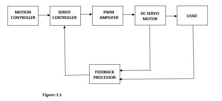
This block diagram explains the processes involve in the system of this project.
It gives a detailed exposition of the different stages of the system and how they combine to function as a whole circuit.
1.3 STATEMENT OF THE PROBLEM
The following are the problem this project is aiming to resolve:
- In accuracy control by human attendants.
- Lack of accurate maintenance.
- High voltage spike and surge.
- High utility rate charges.
- In ability to control output.
1.4 AIM AND OBJECTIVES OF THE SYSTEM
The aim of this project is to implement a system that will serves as a replacement to human effort an automatic regulation control system and Purpose of Servomechanism:
- Accurate control of motion without the need for human attendants (automatic control),
- Maintenance of accuracy with mechanical load variations, changes in the environment, power supply fluctuations, and aging and deterioration of components (regulation and self- calibration),
- Control of a high-power load from a low-power command signal (power amplification) and,
- Control of an output from a remotely located input, without the use of mechanical linkages.
- SIGNIFICANCE OF THE STUDY
- In accuracy control is a primary significant advantage; the implementation of servomechanism system will ensure accurate maintenance and adequate control output supply at the needed time required.
- The application design of servomechanism will save time, minimizes cost and maximize rapid output result of effectiveness without “error signal.
- The application is amplified and will be used to drive the system in the direction necessary to reduce or eliminate the error
1.6 SCOPE OF THE DESIGN
This project entrails the design of application servomechanism system with a close loop feedback and specification that suits a regular laboratory demand. Also, detail explanation will be given in order to buttress the technology of the design. It will explain how application servomechanism system function, the principle behind it operation in control engineering.
DOWNLOAD COMPLETE PROJECT NOW
DOWNLOAD COMPLETE WORK- For Reference Only: Materials are for research, citation, and idea generation purposes and not for submission as your original final year project work.
- Avoid Plagiarism: Do not copy or submit this content as your own project. Doing so may result in academic consequences.
- Use as a Framework: This complete project research material should guide the development of your own final year project work.
- Academic Access: This platform is designed to reduce the stress of visiting school libraries by providing easy access to research materials.
- Institutional Support: Tertiary institutions encourage the review of previous academic works such as journals and theses.
- Open Education: The site is maintained through paid subscriptions to continue offering open access educational resources.